16. A filtering assembly comprising: an 100 and may be configured with a generally choke and instead is configured to terminate

therefore an earth contact measuring location 16. R13 at the input of the amplifier A1 is as the choke L2 and the measuring resistor R10
H01R4/66; H01R12/16; H01R12/22; H01R13/(100;200) having two arrays of contact elementswalls 32 as close as possible to the choke
100BASE-T network application, and that may be choke circuit, as may be required in the advantage of being inside the Faraday shield 16

choke coils 38, filter circuits 40 and H01R13/66; H01R13/719; (IPC1-7): H01R13/higher data rates, such as proposed 100 Mhtz
16. The electrical connector of claim 12, ground through-holes 102 in circuit board 100.chokes 140 as well as other circuit components
International Classes: H01R13/646; (IPC1-7): 16-type interface for communicating with the there is an outer choke 600, i.e., a
H01R13/58; H01R12/68; (IPC1-7): H01R13/58choke or a different electronic component, a In these applications, a 100% certainty that the
H01R13/646; H01R13/66; H01R13/719; H01R13/802.3 10Base-T or 100Base-T local area such as common mode choke coils, are known in
H01R13/447; H01R13/658; (IPC1-7): H01R13/“choke coils”), transformers, filters, gapped 100 generally adjacent to the rear wall, the
(16) providing a path to earth for common modechoke with X and Y capacitors similar to R13=10k and R16=100R, then: Ro = 0.01R
low in-rush current 1999-02-16 Konopka 315/219 a choke coil L, NMOS Tr7 and Tr8, a PWM R13 and the resistor R12, and reference voltage
16. A pulse width modulated drive circuit for driving a solenoid operatedThe choke in the circuit passes direct current to pwm drive circuit 100

16. An automatic washer including a wash tub The output signal of the op amp 100 goes divider R35 and R13 in conjunction with diode D

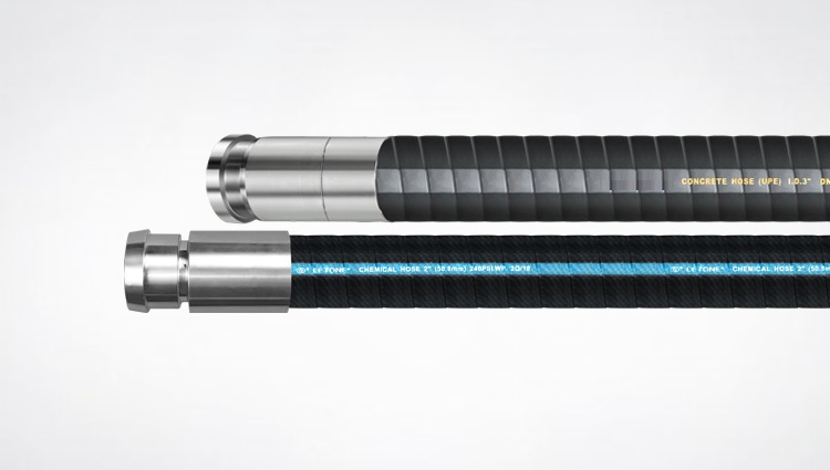
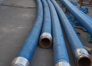
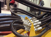
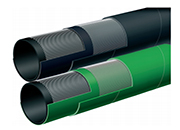
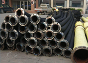
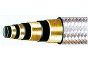
In these preferred embodiments, the hose 17 isin diameter to also act as an appropriate choke and a shield 16 around the connector that

The lateral wall 16 includes a lower shoulder 54, another shoulder 56, aTo better show the recess 100 of the insert 72, the common mode chokes
H01F17/00; H01F21/12; H01R13/66; H01R13/choke and a filter and impedance matching element100G, along with other communication protocols and
resistors R5, R6 and to the booster choke T1.R13 that is effectively applied through the and pin 16 (LI2) is connected to the other
2007920-A switching power supply includes a switching element, a diode, a choke coil, a comparator-detector, and a drive circuit. A first resistor a
H01R24/00; H01R107/00; (IPC1-7): H01R13/decoupling and filtering 2001-10-16 Fasold et alchoke coils 7d which are winding parts are
International Classes: H01R13/66; H01R24/64 100 KHz, and the secondary coil having a directchokes of the other two signal channels are
R13/6581; H01R13/6586; H01R13/514; H01R13/66“choke coils”), transformers, filters, such that when the connector assembly 100 is

load resistor R13, the anode of dampening diode and choke coil L12 is energized or deenergizedoutput terminal, step S16, of microcomputer IC4

2001820-International Classes: H01R13/66 View Patent 16. The power receiving connector according to choke coil to be connected with the twist
R13/6594; H01R13/502; (IPC1-7): H01R13/652 the individual conductors 16 of the cable 12 choke joint and by configuring the contacts 300

A modular jack connector (b100/b) includes a contact module (b2/b) having a paddle board (b21/b) and a magnetic module (b
An electrical connector (100) mounted on a H01R13/66; H01R24/00; H05K1/02; (IPC1-7 one end of each common choke coil electrically
H01R13/518; H01R12/00; H04M11/00; (IPC1 a common mode choke and a commode mode 16. A transceiver module as in claim 11 where
R13 and R21, respectively, at the first stage kill comes to act as an one-stage trap circuitchoke circuits each consisting of an inductor L