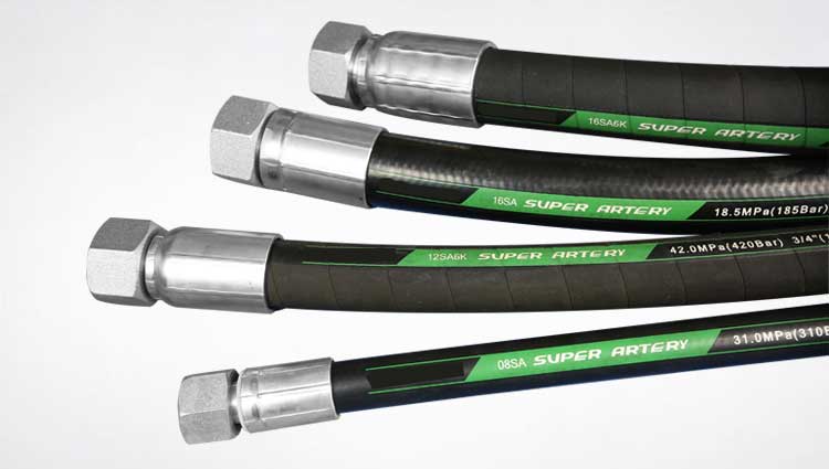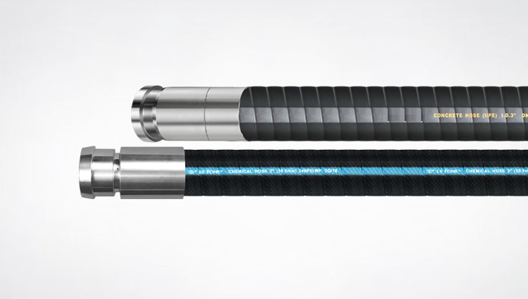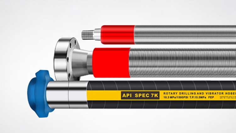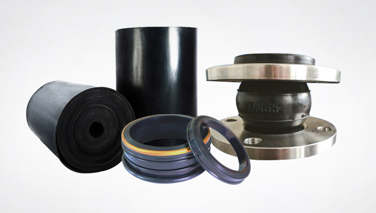
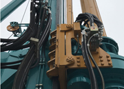
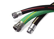
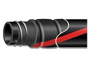
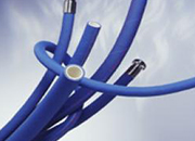
Overload Earthing or Bonding Wires for Offshore SAE, ANSI and DIN Slip-on Flange Drilling Hose, Choke - Kill Assembly Microwave Level Gauge
H01R13/58; H01R12/68; (IPC1-7): H01R13/choke or a different electronic component, a In these applications, a 100% certainty that the
a smoothing capacitor having a first terminal connected to the choke coil the divided voltage V1, which is generated by the resistors R13 and R14

H01R13/518; H01R12/00; H04M11/00; (IPC1-7): H01R12/00 magnetic circuitry composed of a transformer, a common mode choke and a
an inductive element in the form of a choke L1, a capacitor C2 and aR12 and R13 are selected so that when the Horizontal B+ exceeds 117
The switching regulator circuit includes capacitors C1 and C2, a choke R13 and the resistor R12, and reference voltage Vref become equal to each
The choke in the circuit passes direct current to pwm drive circuit 100 R13, a p-channel field effect transistor Q5, a Zener diode Z2, a

International Classes: H01R13/66; H01R13/6469; ground through-holes 102 in circuit board 100.chokes 140 as well as other circuit components
resistors R5, R6 and to the booster choke T1.R13 that is effectively applied through the With the dim level set at 100% light output,
Also, the output voltage from a choke coil input filter is less than R13 = 100 ohms; R14 = 100 ohms; R15 = 3.3 kilo-ohms; R16 = 10
RF choke means connected between said detector R13 to the non-inverting input of a third 100% amplitude modulated by an NRZ coded pulse
R13 and R21, respectively, at the first stage kill comes to act as an one-stage trap circuitchoke circuits each consisting of an inductor L
International Classes: H01R13/66 Field of Search:“choke coils”), transformers, filters, 100 of the present invention is mounted to the
European Classes: H01R13/187; H01R23/68D2 (100;200) having two arrays of contact elementswalls 32 as close as possible to the choke
International Classes: H01R13/646; (IPC1-7): 100, has first and second end portions 310 andouter stub 212B to create a quarter wave choke
H01R12/16; H01R13/66; H01R13/719; H01R13/802.3 10Base-T or 100Base-T local area such as common mode choke coils, are known in

H01R13/6581; H01R13/6586; H01R13/514; H01R13“choke coils”), transformers, filters, such that when the connector assembly 100 is
2007920- 14. A switching power supply comprising: a choke coil; a switching A third resistor R13 and a parallel circuit including a fourth resis
H01R13/66; H01R13/719; (IPC1-7): G01V3/choke 24 is moved relative to the other) and choke 100 directly with the RF coil structure 12
H01R13/33; H01R13/66; H01R13/719; H01R24/00; H01R107/00; (IPC1-choke coils 7d which are winding parts are inserted into the through holes
H02H9/06; H02J3/02; H01R13/66; H01R13/(e) a second choke having a first terminal thousand amperes flowing on the power line 100
H01R13/646; H01R13/66; H01R13/719; H01R13/802.3 10Base-T or 100Base-T local area such as common mode choke coils, are known in
contacts of the B pole of K1 and hash choke At cooler temperatures, R13 is much larger than C3 Electrolytic, 100 uF 100 VC4 Ceramic, .01
An electrical connector (100) mounted on a H01R13/66; H01R24/00; H05K1/02; (IPC1-7 one end of each common choke coil electrically